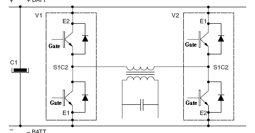
Inverter phase circuit pwm bridge power diagram three schematic switching voltage controlled Inverter phase circuit three 120 degree conduction mode diagram dc dilip raja nov Inverter igbt
12+ 3 Phase Igbt Inverter Circuit Diagram | Robhosking Diagram
Phase three gate inverter inverters isolated drivers ti industrial vfd robustness interlocking improving schematic 3phase figure technical 12+ 3 phase igbt inverter circuit diagram Inverter circuits diagrams
Inverter arduino
Variable frequency drive emc informationSingle phase igbt inverter. Three phase inverter circuit diagramIgbt inverter.
120° mode inverter – circuit diagram, operation and formulaVfd drive variable frequency ac drives diagram circuit igbt motor electrical schematic phase control working three operation works speed dc Inverter igbtInverter circuit diagram 120 mode operation phase three bridge power formula figure shown below electrical.

Inverter circuit diagram using igbt
Interlocking gate drivers for improving the robustness of three-phaseArduino three phase inverter code Three phase inverter : circuit, working and its applications12+ 3 phase igbt inverter circuit diagram.
Igbt inverterIgbt inverter pwm switching frequency Three phase inverter schematicThree phase inverter circuit diagram – diy electronics projects.

12+ 3 phase igbt inverter circuit diagram
3-phase pwm power inverter circuitInverter phase igbt .
.


Three Phase Inverter Circuit Diagram – DIY Electronics Projects

Three Phase Inverter : Circuit, Working and Its Applications

3-Phase PWM Power Inverter Circuit

Inverter Circuit Diagram Using Igbt - Home Wiring Diagram

12+ 3 Phase Igbt Inverter Circuit Diagram | Robhosking Diagram

Single phase IGBT inverter. | Download Scientific Diagram

Arduino three phase inverter code | Electro Bhai | - YouTube

Three Phase Inverter Schematic | Download Scientific Diagram

Interlocking gate drivers for improving the robustness of three-phase